Support & Downloads
All support documentation, video instructions and maintenance information can be found on this page
All support documentation, video instructions and maintenance information can be found on this page
D400 Lite Manual (also applicable for the D400)
The D400 Lite is robustly engineered and should give years of trouble-free service.
Bearing life in normal windspeed conditions is expected to be in excess of 10 years. Shaft seals may benefit from replacement after five years. The yaw bearing brushes should not require replacement during the life of the machine. The alternator itself is hermetically sealed against moisture ingress. Routine maintenance would consist of periodically examining the blades for signs of damage. Blades exhibiting chips or nicks should be replaced.
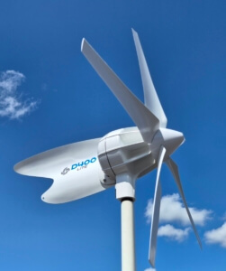
The D400 Lite is extremely efficient by design, making it the most powerful and productive wind generator of its rotor size currently available.
The D400 Lite should perform in line with, or exceed, the values given in the output graph.
 When verifying system performance, it is important that wind speed measurements are taken at the same height as the turbine – do not rely on the wind speed reading of a masthead anemometer, it can be TWICE the speed of the wind at the turbine.
Note that the batteries should be at least 40% discharged.
Note also that if a regulator is installed as part of the system, dumped output will not be seen by shunt-sensed battery monitors.
Should outputs be well below expectations, first suspect turbulence in the wind stream.
Turbulence at a given site can be specific to a particular wind direction where it is caused by an obstruction either up or downwind of the turbine. When the wind direction changes, and the obstruction is no longer in line with the turbine, outputs may return to expected levels. If the turbulent wind stream is not from the prevailing wind direction, this may not be important. Alternatively, the D400 Lite could be re-sited or raised in height.
If poor output cannot be attributed to site conditions, re-check the whole installation against the wiring diagram and also look for poor or loose connections.
Check that the relevant connection from your D400 Lite to the batteries is made to the non-battery side of the battery monitor shunt. If the connections are made direct to the battery terminals, bypassing the shunt, the ship’s battery monitor will not be able to read the D400 Lite output.
Note, where batteries are in a good state of charge, power diverted by the regulator to the dump resistors will not be seen by the battery monitor.
Finally, ensure that the 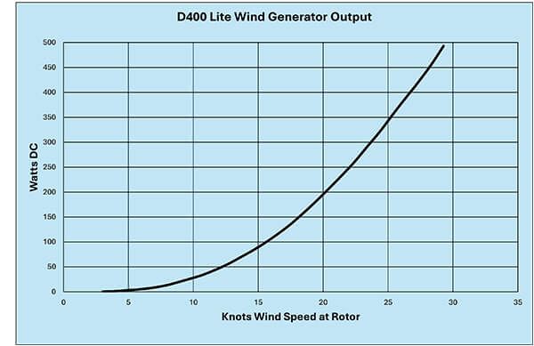 battery bank is in good condition. Check individual battery terminal voltages within the bank. Defective cells within a battery bank are a common cause of poor charging performance.
Note that there is a short period of ‘running in’ with a new wind turbine. The bearings and shaft seals of a new machine take 40 – 50 hours of operation before mechanical friction falls to its design level. As a result, your D400 Lite may seem a little slow to respond in light winds until this ‘running in’ period has passed.
Before deciding that your D400 Lite is faulty, please work through the troubleshooting guide on page 16. In our experience the vast majority of problems reported prove to be faults in the installation rather than a problem with the turbine itself.
Please feel free to contact us if you require additional advice or guidance.
Points to check if you think there’s a problem
• Spin the blades by hand – they should rotate smoothly and freely with no hard 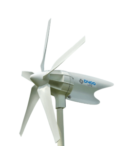 spots.
• Listen for any grinding, scraping or rumbling noises – these would indicate failed bearings or contact between rotating parts inside the alternator.
• Note: if the rotor rotates smoothly and silently, but feels stiff (like turning something in glue), refer to the electrical section on short circuits.
• Next, try rotating the D400 Lite around its yaw axis. Again, it should turn smoothly and freely with no hard spots. If the yaw action is stiff or accompanied by undue noise, suspect the yaw bearings or the bush and slip ring assembly (see electrical section below).
• Check that the blades are fitted the right way round, with the concave surface facing forward, i.e. towards the wind.
• Also, establish that the hub is secure on the alternator shaft and that the rotor does not ‘wobble’ due to wear at the hub.
• Finally, check that all fasteners are tight and secure.
Very often poor turbine performance is traced to a problem elsewhere in the installation rather than a fault with the wind generator itself.
• First check that both the D400 Lite and the regulator are the correct voltage for the electrical system. Both items have identification labels showing the voltage, typically 12 or 24 volt.
• The most common cause of low outputs is loose or corroded connections in the output cabling. Check and re-make all connections from turbine to battery. Seawater and electricity are not a good combination, and connections deteriorate very quickly when wet.
• Next, check the turbine by measuring its open circuit voltage. Disconnect the unit as close to the turbine as possible. If it is not too difficult, remove the turbine from its tower and measure at the fly lead cables exiting the yaw shaft of the machine itself.
• With a mustimeters set to the 20 volt DC range, connect the red positive meter lead to the red output, the black meter lead to the black output, and spin the unit by hand. On a 12 V D400 Lite, you should be able to produce 4, 5 or even 6 volts, depending on how hard you spin. If you see voltages in this range, then the D400 Lite is probably OK. If the D400 Lite has an internal fault such as a missing phase in its alternator, then you will not be able to produce more than one or two volts.
• Assuming the output voltage is OK, try rotating the yaw shaft (where the cables exit) whilst continuing to spin the rotor. If the voltage varies or disappears as you rotate the yaw shaft, the brushes and slip rings require cleaning. Equally, if the voltage remains steady, but the yaw shaft is unduly stiff or squeaks when rotated, the brushes and slip rings would benefit from cleaning.
• If the turbine checks out OK on the voltage test, suspect the rest of the installation. Check each wiring connection for corrosion, tightness and security as well as the fuses, fuse holders etc.
• If a regulator bypass switch is incorporated within the installation, check that this is wired in accordance with the diagram contained in the D400 Lite regulator instructions. Note that a similar switch can be used as a braking switch, and the wiring for this is shown on page 12 of the D400 Lite User’s Manual. Ensure that the two uses of a switch have not been confused.
• Note that the ship’s battery monitor is driven by a shunt, which will be mounted close to the batteries. Ensure the D400 is connected to the non-battery side of the shunt. If it is not, then the D400 Lite output will not be seen by the meter.
• Also, the D400 Lite regulator incorporates a charge splitter (i.e. has two outputs). If one of these is connected to the service battery bank and one to the cranking battery or windlass battery, it is possible that power from the D400 Lite is flowing to them in preference to the service bank.
Try connecting both regulator positive outputs together and on to the service bank to see if that improves matters.
• Finally, put a dedicated ammeter in the positive line between turbine and regulator. This should read all current from the D400 Lite, including any diverted to the regulator dump loads.
**Warning – dismantling your D400 Lite alternator voids the warranty.
Ensure warranty labels remain unbroken.**
● Stiffness in yaw; the D400 Lite will not rotate to face the wind – check for any physical obstructions and the action of the yaw shaft. If the yaw shaft does not rotate freely, suspect damaged or corroded yaw bearings, damaged or corroded slip rings/brush assembly or possibly a bent yaw shaft.
● Erratic yaw action; the D400 Lite turns off the wind and is unstable
– the D400 Lite is normally very stable in yaw. If the turbine appears to ‘hunt around’ its axis, this could be due to turbulence in the airflow. If so, the problem should disappear when the wind changes direction or the yacht is in a different location. Check that the D400 Lite is properly secured to the mount tower. There should be no undue play between the turbine and the tower. Also, ensure that the tower is vertical and sufficiently rigid. If the tower is too flexible and bends excessively under wind loading, it should be braced or guyed to stiffen it.
● Open Circuit; this is a major cause of poor yaw action, indicating that the turbine is not properly connected to the batteries.
– in this open circuit condition, the air rotor will over speed and the air blades will become uncharacteristically noisy, emitting a whistling noise. The D400 Lite will frequently turn off the wind, rotating through 360 ° on occasion. Check all wiring, looking for poor or broken connections. Also check fuses. If the fault remains, bypass the regulator to rule out regulator malfunction as the cause of the problem.
● Intermittent or occasional erratic yaw action
– this could be due to an intermittent electrical fault. If you observe turbine output abruptly dropping out and then suddenly returning, this could indicate a poor connection between the brushes and slip rings.
To service, remove the four self-tapping screws that secure the black brush-holder plate. Remove the brush-holder plate, taking care not to displace the brushes or brush springs.
The slip rings and contact faces of the brushes can then be cleaned with a solvent- soaked cloth or fine, wet and dry paper.
● Squeaking or grating noises audible in yaw
– this could be caused by damaged yaw bearings. More typically, it is caused by dirt or corrosion on the slip rings/ brushes.
Remove the brush-plate as above. If noise is still present with the brush-plate clear of the housing, suspect yaw bearings. If the squeak has gone, it confirms the noise emanates from the brush and slip ring assembly. Clean these parts as in the last section. Also, using a fine file, remove any sharp edges from the contact surfaces of the brushes.
On re-assembly, the yaw shaft should rotate silently. If a squeak is still evident, remove the brush plate again and spray the slip rings and brushes with an electrical lubricant (WD40 or similar) or smear a little silver-loaded grease on the slip rings.
• Noise or vibration transmitted down the shaft – suspect a loose rotor. Grasp an blade and rock the rotor to check if there is any relative movement between the rotor and the alternator shaft. If play is felt, remove hub parts and re-build, fitting a new hub centre.
• Correct fit of nose cone – check that the nose cone is not catching on the alternator housing.
• Blade damage – check that the blades are not damaged or chipped. This may put the rotor out of balance. Replace blades as necessary.
• Tail bolts – check tail bolts are tight.
• Noises from the alternator – rotate the blades slowly and listen at the alternator housing. Grating or scraping noises indicate a fault within the alternator. Refer to your dealer or Eclectic Energy Limited.
DuoGen Schematic Short Tower (10601)
DuoGen Schematic Long Tower (10599)
DuoGen Schematic Extra Long Tower (10600)
The DuoGen is designed to require minimal maintenance, but a little attention will pay dividends in terms of appearance and performance.
If the yaw action becomes stiff and unresponsive periodic washing with fresh water will remove accumulated salt deposits and keep the yaw bearings and the telescopic drive shaft sliding smoothly. An occasional application of a domestic silicone- based polish on the tower tube and drive shaft is also recommended.
The alternator requires no maintenance as it is hermetically sealed, and the bearings are protected by a twin lip radial shaft seal.
The water mode is robust and efficient, and maintenance free as the impeller transmission device is lubricated by a combination of synthetic oil within the matrix of the bearing material and water.
When dry following immersion in sea water, the unit may feel a little stiff. This is due to dry salt deposits and the unit should free up immediately it is returned to the water.
However, the DuoGen’s water impeller rotates about 5 million times for every thousand miles sailed, and like all mechanical devices, it is prone to wear.
We recommend that the transmission elements are replaced every 8- 10,000 nautical miles, or 40 – 50 million revolutions, in order to maintain optimum performance. This is a straightforward procedure that can be undertaken by the owner.
The DuoGen’s air mode transmission device incorporates a heavy duty gear set and thrust bearings, all running behind grease seals.
The gear faces benefit from the occasional light application of a good quality weather resistant grease, as supplied.
The DuoGen is designed to be easily retro-fitted to yachts and multihulls. This represents a substantial challenge because yachts vary widely in size, performance and form.
To accommodate the differences in size, the DuoGen is available in three different tower lengths, short, long and extra- long. The appropriate tower length depends on the yacht’s transom height. This ensures that the angle of the water mode keeps the water impeller immersed, despite heel angle and wave action. It also ensures that when the DuoGen is changed to wind mode, there is sufficient clearance under the air blades for crew safety.
For each tower length we recommend a maximum and minimum mount height above the static water line. We also recommend that where possible, installations are kept within 800 – 900 mm of the yacht’s centre line. This keeps the running depth of the water impeller within the optimum range, regardless of tack.
Note that the majority of DuoGens are installed alongside self-steering systems. The two technologies complement each other, and assuming they are installed 600 – 700 mm apart, will not interfere with each other’s operation.
The table below offers a guide as to which variant is best suited to different yacht sizes. Note that there is considerable overlap and this reflects different hull designs in terms of length over all and freeboard.
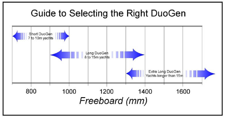
Other factors can also affect tower length choice. For example, where a 38 foot yacht is fitted with a stern arch, the extra-long DuoGen may be preferred to the long because it provides greater clearance above the arch for the air rotor. Equally, a 55 foot yacht that only wished to use the DuoGen in water mode could fit the short tower machine, and simply mount it lower on the transom.
The DuoGen is supplied complete with standard mount hardware. This bracketry is designed to accommodate most yacht transoms, and offers a simple and flexible approach to mounting. The bracketry has a range of adjustment and is usually sufficient to achieve an excellent and robust installation. .
Where additional bracketry is required, as is the case with canoe stern yachts and some multihulls, Eclectic Energy can offer advice and bespoke parts.
One of the DuoGen’s key benefits is that most of the system’s weight, i.e. the alternator, is at coaming level. This remains the case in both water and wind mode. Consequently, when operating in wind mode, the mounting only has wind loadings to resolve, not the mass of an alternator.
Installing a conventional wind generator involves a dedicated mount tower and substantial braces fore and aft and athwartships. The cost and weight of this structure is avoided with the DuoGen.
The DuoGen is supplied with full installation instructions. However, it is not always easy to visualise how and where the DuoGen could be mounted, and what clearances will exist when it is operating or being changed from one mode to the other. For this reason we encourage anyone considering a DuoGen installation to contact us and provide a photograph of their yacht’s stern. We then discuss installation options and implications. This is particularly important where a yacht has no push pit rails or has davits or backstays that are secured at the base of the transom.
The mount bracketry incorporates the upper and lower attachment points for the DuoGen. Once the brackets are in place, the DuoGen is installed and secured with a single M10 pivot pin at the alternator, and its tower secured with the upper releasable clamp. This makes it very simple and straightforward to remove the DuoGen for a weekend’s racing.
The electrical output cable is usually taken into the yacht via a cable gland and hard wired within the stern locker / lazarette area. Deck plugs and sockets are not recommended due to the potential shock hazard should they become disconnected.
View the Short Tower Schematic | View the Long Tower Schematic | View the Extra Long Tower Schematic
The DuoGen was specifically designed to maximise zero carbon electricity generation on cruising yachts. The DuoGen’s unique wind/water capability works best where cruising yachts are making frequent or long sea passages, interspersed with periods at anchor or in harbour.
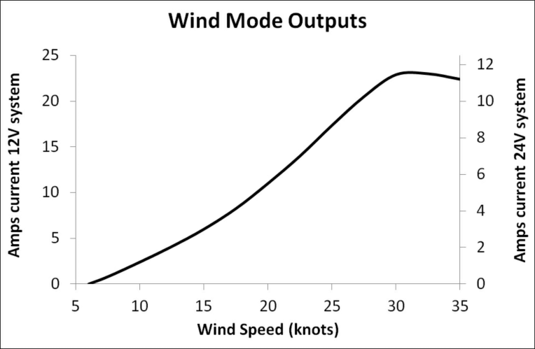
The DuoGen should perform in line with the values given in our published output graphs. However, when monitoring the system, external factors can effect performance, and that may lead you to falsely conclude that there is a problem. To assist in accurate evaluation, particularly in relation to wind mode, be aware of the following:
● When monitoring the wind mode, wind speed measurement should be made at the height of the turbine rotor. Where a mast head anemometer is used, there will be significant wind shear, and it is not unusual for wind speed measurements at turbine level to be 30-50% lower than at the masthead. This is particularly true in harbours and marinas.
● When measuring performance, battery state is also important. Fully charged batteries do not readily accept current, and where a charge regulator is fitted, any dumped power will not be registered by the ship’s battery monitor. In addition, where batteries are fully charged, or the regulator is ‘dumping’, the load seen by the DuoGen’s alternator changes. This makes the alternator ‘stiffer’ to turn, which in turn increases the force which furls the turbine. The increased furling angle reduces the intercept area of the DuoGen’s air rotor which in turn lowers the electrical output.
When evaluating the DuoGen’s air mode, try to ensure batteries are 30 – 40% discharged, or alternatively switch on numerous electrical loads in order to pull the battery voltage down.
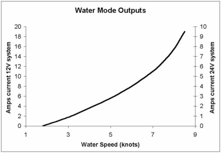
● If wind mode outputs remain below expectations, first suspect turbulence in the wind stream. Turbulence at a given site can be specific to a particular wind direction where it is caused by an obstruction either up or downwind of the turbine. When the wind direction changes, and the obstruction is no longer in line with the turbine, outputs may return to expected levels.
● If poor output cannot be attributed to site conditions, re-check the whole installation against the wiring diagram and also look for poor or loose connections. Also, check fuses and fuse holders.
● Finally, ensure that the batteries are in good condition and of sufficient capacity. We recommend a minimum of 300 Ah for use with the DuoGen.
 If you still suspect a problem with the machine, consider the following:
● Do the air blades spin freely? The air rotor should spin without any undue noise or friction. If not, is there a braking switch engaged or could there be another short circuit in the output cables? (Make sure you disconnect the batteries before trying to find out!)
● Is the DuoGen free to move about its yaw axis? It should move easily with no undue noise or friction.
If in doubt, please contact us.
Note that there is a short period of ‘running in’ with a new wind turbine. The bearings and shaft seals of a new machine take 40 – 50 hours of operation before mechanical friction falls to its design level. As a result, your DuoGen may seem a little slow to respond in light winds until this ‘running in’ period has passed.
*All performance figures are indicative. Actual outputs may vary. E&OE.
Noise and Vibration in Air Mode
The DuoGen has been carefully designed to minimise noise and vibration. This is particularly important when equipment is operating in close proximity to people.
A certain amount of noise and vibration is unavoidable with any rotating machinery. However if your DuoGen is uncharacteristically noisy, check the points below.
● Identify where the noise is coming from. It can normally be determined whether noise is emanating from the alternator or air drive, i.e. top or bottom of the machine.
● To check the condition of the air drive ‘rotate’ the air blades. They should rotate easily and smoothly with no hard spots. Caution do not attempt this in strong breeze, or allow the air blades to accelerate in the wind.
● Check that the gear cover is not in contact with the hub. If it is, remove the gear cover which is secured by two M4 alan head screws. Straighten the gear cover bracket and refit the cover.
● If roughness or hard spots are felt when rotating the drive, remove the gear cover and examine the gear teeth. Note, a metal gear runs against a nylon gear. Check for wear on the gear teeth and replace worn gears as necessary. If the gear teeth appear serviceable, clean the gear faces of old grease and dirt, and apply fresh grease. This
should restore quiet operation. If the air drive remains noisy, check the backlash between the gear faces and adjust if necessary.
● If the noise does not emanate from the air drive, check the upper tower bearing. This is the beige coloured, spherical bearing at the top of the main tower through which the stainless steel outer drive shaft sleeve runs. Note, the bearing surface itself is a grey coloured, ‘high speed’ bearing liner. If there is undue play at this top, check that the bearing liner is still in place.
● At the lower end of the outer drive shaft, a rubber-lined stainless steel coupler is used to connect the telescopic drive shaft to the alternator shaft. Later models (DG3) feature a one piece nylon combined reducer and coupler. To access this, remove the main tower. Check the condition of the coupler and ensure the lower M6 securing bolt has not been over tightened. If this bolt is fitted incorrectly, it can pull the drive shaft off centre, causing vibration and uneven running.
● With the main tower and drive shaft removed, try rotating the alternator by hand. It should rotate smoothly and quietly. If it feels ‘heavy’, like turning something in glue, suspect a short circuit and refer to section on electrical faults. If there is any roughness or hard spots, suspect a mechanical fault. This could be due to failed bearings or mechanical contact between internal rotating parts. The alternator must be dismantled to replace the bearings. Alternatively, the alternator can be returned to a dealer or Eclectic Energy for service.
● Poor installation or loose mounting can be a source of noise and vibration. Review the section of this manual on installation, and check all fasteners for tightness. In some cases, particularly in lightly- built yachts with thin, resonant panels, it may help to place a substantial plywood backing pad behind the universal bracket foot. Should the yacht’s pushpit be unduly flexible, an additional stiffening strut can be added to the mounting, running from the universal bracket to the coaming or the deck, just forward of the coaming.
● Ensure that the yoke lock is applied when operating in wind mode.
Excessive furling in wind mode
● The DuoGen is designed such that the yaw arm and air rotor will progressively turn away from the wind as wind speeds increase. This reduces the intercept area of the rotor, from a full disc in lower winds, to an ellipse of reduced area in high winds. Due to the cubic relationship between wind speed and energy, electrical outputs will continue to rise. However, the furling does moderate the wind loadings on the DuoGen, and on the yachts moorings.
● The furling is a result of the balance between the torque reaction resulting from back EMF within the alternator (i.e. how hard it has to work to drive the charging current) and the pressure of wind on the rotor disc and the yaw arm. Anything that makes the alternator ‘stiffer’ to turn will increase the furling force.
● Mechanical friction – undue friction in the air drive, drive shaft or alternator can produce excessive furling, Refer to previous section to evaluate.
● Electrical influences – the DuoGen will furl least when open circuit, or running into a deeply discharged battery bank. As the batteries approach fully charged, the furling angle will increase. When the charge regulator is acting, this connects the dump load,resistors changing the electrical load the alternator is working into. This will also result in an increase in the furling action.
Note, by using the yaw arm’s springer plunger to lock the tower, the furling action can be disabled. This will generally result in increased outputs, but is only viable when the yacht is lying to an anchor or mooring and is free to ‘weathercock’ i.e. keep her bow to the wind.
System Performance
1) Unlike many other grid tied micro generation systems, StealthGen power electronics are wholly powered by DC power from the wind turbine. Other systems power the electronics from the mains and this means a continual, albeit low, draw from the grid even during periods of low or zero wind. StealthGen draws nothing from the grid in these conditions.
2) Airborne noise – the StealthGen wind turbine should be virtually inaudible in normal operation. Typical sound emission levels are between 30 – 40 db. If there is a distinct whistling or shrieking noise from the air blades, this could indicate that the turbine is over speeding due to a fault in the system (i.e. an open circuit condition caused by a poor connection). Erratic yaw behaviour, where the turbine keeps turning away from the wind, is also symptomatic of a possible open circuit fault.
3) Vibration and mechanically transmitted noise – in normal operation, there should be very little noise or vibration evident inside the building. If noise and vibration are continually present, this may indicate a turbine fault such as a loose or worn air hub, a damaged air blade or failing bearings. Occasional vibration, associated with very high or gusty wind, is probably due to resonance in the turbine tower. This can be addressed by adding stays to the tower to prevent its flexing, or by reducing the height of the turbine (i.e. shortening the tower) or by using a stiffer tower tube.
4) Power Output – the output from a micro wind system varies continually due to fluctuations in wind speed and direction. For this reason, many conventional cumulative kW hour meters fail to record system output accurately, and typically substantially under read. Power meters with a high sample rate are required for accurate metering. Refer to Eclectic Energy Limited for further information.
5) Multiple systems – two or more StealthGen turbines can be successfully installed where more power is required. Turbines should be mounted at least 2.75 metres apart where the turbines are perpendicular to the prevailing wind direction. This spacing should be increased to 4 metres plus where the turbines are in line with the prevailing wind, and also the mount height raised if possible. Avoid mounting in the centre of flat-roofed buildings. Always aim to mount at a point nearest to the direction of the prevailing wind.
Performance and Power Output
Refer to D400 manual for the wind turbine power curve. Estimated annual power yields are represented below.
Th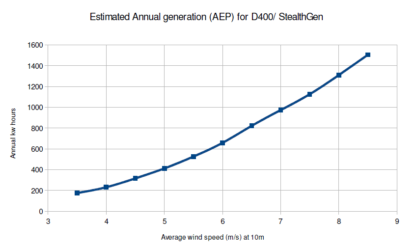 e StealthGen / D400 wind turbine is very robustly engineered and will operate safely in all typical wind speeds. It is generally preferable to allow the turbine to operate normally even in very high winds.
The brake switch on the control/ interface unit may prove ineffective in wind speeds above 18m/s (40 mph), and should therefore not be used in these conditions as damage to the turbine can result. Also the brake switch should not be treated as a parking brake for the same reason.
Refer to the D400 Manual for further information on the brake switch and high wind speed strategies.
*All performance figures are indicative. Actual outputs may vary. E&OE.
The Sail-Gen Lite is built from high quality and corrosion-resistant materials. The unit is designed to require minimal maintenance, but a little attention will pay dividends in terms of appearance and performance. The alternator requires no routine maintenance and is hermetically sealed.
The alternator is fitted with rubber-shielded, stainless steel bearings which are protected by a twin lip, radial shaft seal. A dry-running spherical, self-aligning bearing is fitted at the top of the tower. Elsewhere, dry-running bearing bushes are used. The water impeller unit utilises a specially designed transmission which presents the impeller perpendicular to the water flow. The transmission element is robust and maintenance free.
It is lubricated by a combination of synthetic oil held within the bearing material itself and water. When dry following immersion in seawater, the unit may feel stiff. This stiffness is usually due to dried salt deposits and the drive should free up when the unit is returned to the water.
The Sail-Gen Lite water impeller rotates about 5 million times for every thousand miles sailed, and like all mechanical devices, the water transmission is prone to wear.
Eclectic Energy recommends that the transmission elements are replaced every 8 – 10,000 nautical miles, after approximately 40 – 50 million revolutions, in order to maintain optimum performance. This is a straightforward procedure that can be undertaken by the owner.
A full range of spare parts are available for the Sail-Gen Lite in our Shop section under Sail-Gen Lite Parts. All spare parts are supplied with fitting instructions.
When installing the Sail-Gen Lite, due care should be exercised at all times. The Sail-Gen Lite weighs 13.7kg and is awkward in shape with the weight concentrated at one end. It is sensible to approach installation in a methodical manner and to enlist some help when attaching or removing the machine from the transom.
If possible, install the Sail-Gen Lite when the yacht is ashore. If this not practicable, installing in a marina with the yacht secured stern to a pontoon is a good alternative. The pontoon provides a safe and convenient working platform.
A dinghy can be lashed across the transom in order to provide additional security, if work has to be done at anchor.
To read more please view our Sail-Gen Lite Manual by clicking here
Reference to the charge current on a dedicated ammeter or battery monitor, in conjunction with a reading of boat speed from the ship’s log, should produce figures which correspond to the published power performance data.
If the charge current appears low for the boat speed, consider the following checks before deciding there is a fault:
● When measuring performance, the state of charge of the batteries should be taken into account. A discharged battery accepts charge current more readily than a charged one.
● When evaluating Sail-Gen Lite performance, ensure that the batteries are discharged by 30 – 40%. Alternatively, switch on multiple electrical appliances in order to reduce the battery terminal voltage.

● Note that where a charge regulator is fitted, it will act to prevent battery damage through overcharging. Surplus power diverted by the regulator to the dump resistors will not be seen by a battery monitor. A dedicated inline ammeter may also show a reduced reading when the regulator is active and the dump resistors are connected. This is because the electrical load provided by the dump resistors retards the alternator, lowering the Sail-Gen Lite efficiency.
● Where low outputs are evident, first suspect loose or corroded connections. Check and re-make these connections as necessary. Also, check the cabling for broken insulation or other damage.
● Ensure that the batteries are in good condition. A defective cell within a
battery will greatly reduce overall charging efficiency.
*All performance figures are indicative. Actual outputs may vary. E&OE.
Mechanical Issues
If the Sail-Gen Lite water impeller continually surfaces and will not ‘re-bury’ check the dive plane adjustment, Also check that the dive plane actuating rod moves freely and returns fully under the pressure of its spring.
Typical operating dive plane angles are between 6-12 degree positive (i.e. leading edge of dive plane lower.) This means the angle between the vertical frame member which carries the water impeller, and the face of the dive plane should be in the range of 96-102 degrees when there is no tension on the recovery lanyard.
If the water impeller continues to surface, check that the alternator pivot point is the specified distance above the static water line, and that the installation is within 500mm of the yachts centre line. Finally suspect turbulent water flow from a rudder or skeg, and re-locate the unit so it operates in clearer water.
Always ensure the ‘C’ bracket/ yoke lock screw has been released prior to deployment and ensure Sail-Gen Lite is free to pivot laterally.
● If power output is low check for weed or debris fouling the water impeller. Also check for undue friction when the impeller is rotated. If the rotation is stiff or hard spots are present suspect bent or damaged drive pins. Also check for axial play at the impeller. There should be 1-2mm of free movement of the impeller along the axle. If this is not present suspect fishing line or similar wound around the impeller shaft at the thrust bearing.
Electrical Issues
● If there is no power output evident first suspect poor or broken connections or blown fuses. To test the alternator disconnect at the end of Sail-Gen Lite output lead. Then connect a multi-meter set to the 0- 20 VDC range connected between the positive and negative cable. Spinning the drive shaft by hand should produce 3-5 volts on a 12 volt machine and 6-10 volts on the 24 volt variant. If you can produce voltages of this order it indicates that the Sail-Gen Lite is OK and the fault lies elsewhere.
● Next check i.e. the charge regulator for a possible fault. The easiest way to do this is to connect Sail-Gen Lite directly to the battery by passing the regulator. If the charging current now flows check the regulator manual and regulator trouble shooting guide (Available on Eclectic website, www.eclectic-energy.co.uk).
If no charging current is shown on the ships battery monitor, ensure Sail-Gen Lite is connected to the non-battery side of the shunt which drives the monitor. Refer to body of this manual for further information.
Also the 6TB12 and 24 type regulators have an integral charge splitting function, i.e. can charge two battery banks simultaneously. If only one battery bank is monitored any ‘missing’ charge may be passing to the other battery bank.
Where the water impeller rotates very slowly but no mechanical friction is evident there may be a short circuit in the Sail-Gen Lite output cables. To check disconnect Sail-Gen Lite at the end of its output cable and see if the rotation frees up. Note – short circuiting the output of Sail-Gen Lite produces on electromagnetic braking effect.
Mon-Fri: 09:00-17:00
Sat: closed
Sun: closed
sales@eclectic-energy.co.uk
Tel: +44 (01623) 835400


Unit 22 Sherwood Network Centre
Sherwood Energy Village
Ollerton
Nottinghamshire, NG22 9FD
Company number 03883495
Place of registration: United Kingdom
