Air has mass. Moving air has both mass and velocity. Wind is moving air and therefore wind contains kinetic energy. The higher the velocity of the wind the greater the kinetic energy it contains.

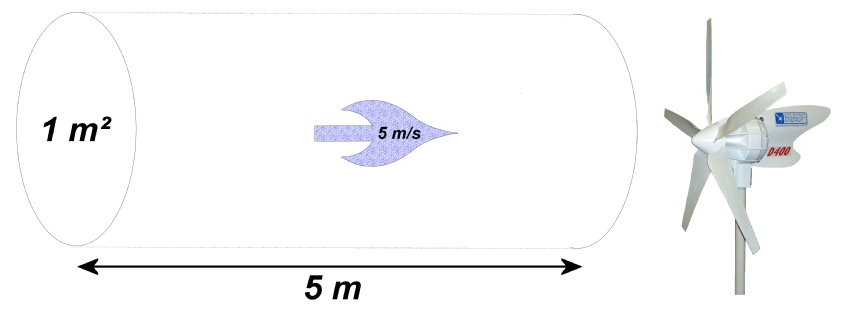
 Consider an Eclectic D400 wind turbine. It has air blades with a diameter of 1.1 metres which sweep out an area of about 1 square metre. Assume the wind is blowing at a velocity of 5 m/s (10knots) and then visualise this as a cylinder of air 1.1 metre diameter and 5 metre long in front of the air rotor. Air weighs about 1.2 kg per cubic metre at sea level, so our ‘cylinder’ of air weighs 6kg. This ‘weight’ of air passes through the air rotor each second, and as it does so, a proportion of the kinetic energy it contains is extracted by the D400’s air rotor. The velocity of the wind is the critical element in this process because higher winds pass a greater mass of air through the air rotor each second (imagine an ever longer cylinder of air!). Because the amount of kinetic energy varies as the square of its speed, this results in a cubic relationship between wind speed and available energy. The effects of this are dramatic. For example there is almost 75% more energy available in a 12 mph wind than at 10mph. Just as available energy rises quickly with increasing velocity, so it diminishes rapidly at low wind speeds.
There is very little useful energy in wind speeds below 6mph (3m/s).
This is the reason commercial wind generators are located on high ground or offshore where a good wind resource is available.
Man has harnessed the energy in wind for millennia. Early wind capture devices were drag machines. Drag machines work by presenting a surface which the prevailing wind pushes against to produce motion.
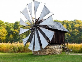
Pamonomes and simple square sails on ships are examples of early devices.
Drag devices are simple to make and can do useful work, but they are not very efficient. More modern examples of drag machines are the Savonius rotor, and the cup anemometer, used to measure wind speed. Savonius type machines are currently manufactured as trickle charge devices for batteries, and at a larger scale as architectural building mount turbines. The limitation of drag machines remains that the surface which is receding from the wind cannot travel faster that the wind. Also as one surface or ‘paddle’ recedes the other must advance into wind.
Although the advancing ‘paddle’ is shielded in the Panemome or of a lower drag shape as in the Savionius the net result is that the overall efficiency of these machines does not exceed 15%.
For this reason most modern machines use aerodynamic lift rather than drag. Aerodynamic lift occurs due to the pressure gradient created by the differential flow of air around a section of a specific shape, for example an airfoil section as in an aircraft wing. When an airfoil is placed at an optimum angle to the wind the airflow passing over the top of the foil is forced to accelerate which reduces its pressure in relation to the slower air which is passing underneath.
The result is a net force which acts on the wing or blade, perpendicular to the relative wind direction. This is aerodynamic lift, and for a well-designed air craft wing or wind turbine blade it is of much greater magnitude than drag.
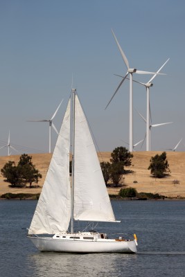
Lift machines are therefore more efficient than drag, types, and also use a lot less material in their construction. Critically the air blades of a modern lift type turbine can rotate with a tip sped many times greater than the true wind speed, just as a modern yacht can sail faster than the wind.
The technical term for this is tip speed ratio or TSR. Modern electricity generating wind turbines are designed with TSR in the range of 4 to 16, with values of 6 to 8 being the most typical. This helps explain why modern commercial wind turbines only have two or three air blades.
Intuitively you would assume that a machine with many blades would capture more of the winds energy than one with two or three slender blades. However taking the multi blade idea to its extreme the entire rotor disc would be covered by blades making it in effect a solid disc. No wind could pass through such a rotor disc and the wind would be stopped at the turbine. No energy can be extracted from stationary air, we require moving air for that. Therefore designers seek to strike a balance between a rotor which completely stops the wind, and one that does not impede the wind at all. They are aiming to extract as much energy as possible whilst keeping the wind speed reduction through the rotor to a minimum.
 This ‘balance’ point is described by the Betz Theorem, which assumes 59% is the maximum extractable energy, with a resultant fall of around 30% in the wind velocity behind the rotor. In practise wind turbines do not achieve the theoretical efficiencies suggested by Betz.
However large commercial turbines can convert up to 40% of the winds energy to electricity and a good micro turbine approximately 25-30%.
The percentage of the available wind energy captured by a turbine is known as its power co-efficient. The overall efficiencies of small devices will always be lower than large ones due to the effect of scale on aerodynamic behaviour.
Wind turbines can be either horizontal or vertical axis.
Horizontal axis wind turbines are the predominate and most commercially successful form. These can be either up wind, where the air rotor is up wind of the support tower, or down wind where the rotor is down wind of the support tower.
Horizontal axis turbines need to pivot or ‘yaw’ in order to keep the air rotor perpendicular to the prevailing wind. Down wind turbines rely on the rotor disc itself to orientate the turbine. Up wind machines usually have a tail to keep the rotor pointed in the right direction.
These are ‘passive yaw mechanisms. ‘Active yaw’ is used on larger turbines where electric motors are used to rotate the nacelle into the wind.
Vertical axis turbines are omni-directional and can accept wind from all directions. They do no require a yaw mechanism. Most drag type wind turbines are of a vertical axis configuration but there are also lift versions, of which the Darrius ‘eggbeater’ type is perhaps best known.
Although vertical axis turbines have intuitive appeal, in practise even the best of the lift types cannot quite match the efficiencies of a horizontal axis turbine of similar size. Also the blades are subject to large centrifugal bending forces and are prone to suffer fatigue failure as a result.
The horizontal axis turbine resolves the operating forces more successfully than the vertical axis configuration, and in general will also self-start more readily in light winds.
Eclectic Office Opening Hours:
Mon-Fri: 09:00-17:00
Sat: closed
Sun: closed
sales@eclectic-energy.co.uk
Tel: +44 (01623) 835400


Eclectic Energy HQ
Unit 22 Sherwood Network Centre
Sherwood Energy Village
Ollerton
Nottinghamshire, NG22 9FD
Company number 03883495
Place of registration: United Kingdom


